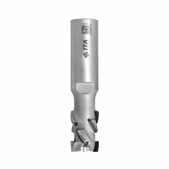
Panel Nesting with Melamine Chipboard: How to Avoid Chipping on Both Faces
Nine causes of melamine chipping in CNC nesting, each with a fix - tooling, feeds and a pre-nesting checklist you can pin to the machine.
Chipping on melamine laminate is the single most common quality complaint in CNC nesting. You load a sheet of Egger or Kronospan, run the programme, and pull parts off the bed to find rough, flaking edges that no amount of edge banding will hide. Sometimes the top face chips. Sometimes the bottom. Sometimes both.
The good news: melamine chipping is not inevitable. It is a symptom with identifiable causes, and every one of them has a fix. This guide covers the nine most common reasons melamine laminate chips during nesting, the tooling that delivers the cleanest edges, and a pre-nesting checklist you can pin to the machine.
Why melamine laminate chips in the first place
Melamine-faced chipboard is a sandwich: a soft, porous core of bonded wood particles, coated on both faces with a thin layer of melamine-impregnated decorative paper. That melamine layer is typically 0.15 to 0.3 mm thick on standard boards — hard, brittle, and bonded under heat and pressure.
When a router bit cuts through this sandwich, the soft core chips away easily. But the melamine skin does not deform — it fractures. If the cutting edge is not sharp enough, or if the geometry pushes the laminate away from the core rather than pressing it in, the melamine cracks ahead of the cut and breaks off in jagged flakes. That is chipout.
Chipping is always about the relationship between cutting forces and the laminate's bond to the substrate. Anything that increases lateral force (wrong geometry, vibration, excessive chip load) or weakens the bond (heat, poor board quality) will produce chipping.
Nine causes of melamine chipping and how to fix each one
1. A dull or worn cutting tool
This is the first thing to check. A sharp edge slices through melamine cleanly. A worn edge tears rather than cuts — the laminate is pushed sideways and breaks off in jagged flakes.
As our ITA Tools technician puts it: "When diamond goes dull, the laminate starts cracking instead of being cut. It is a very sudden change — one day it is fine, the next day every edge is rough."
The fix: Establish a tool-change schedule based on linear metres, not calendar time. Monitor spindle amperage — a rising load at the same feed rate signals wear. Do not push a dull PCD bit "one more shift." Running a worn diamond insert risks shattering the brazed tip, turning a resharpening job into a full replacement.
2. Wrong tool type for the application
A standard upcut spiral pulls chips upward — clean bottom face, but it rips the top laminate away from the substrate. If you are using an upcut spiral on double-faced melamine board, this is your answer.
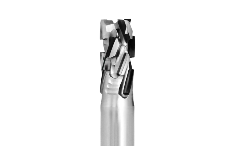
The fix: Use a PCD nesting bit with axial-angle inserts (DTE or DTM) or a compression router bit (X90 or X99). Both geometries press both laminates into the core during cutting. See our guide on compression router bits for a detailed comparison.
3. Feed rate too high
When chip load gets too high, the cutting edge cannot sever the melamine cleanly — it tears chunks away, worst on the exit side of each insert.
The fix: Reduce feed rate in 1 m/min increments and inspect edge quality after each test cut. For PCD nesting bits in 18 mm melamine chipboard, 15-20 m/min is the reliable range. Above 20 m/min, the DTM Z3+3 handles high feed rates better than any other PCD nesting bit in the range.
4. Feed rate too slow
This surprises operators who assume slower is safer. When feed rate is too low relative to spindle speed, each edge rubs instead of cutting. Friction generates heat, which softens the resin bond between the melamine and the core. The laminate lifts, and the next edge catches the lifted flake and tears it off.
The fix: Keep chip load per tooth within the manufacturer's range. Most 12 mm PCD nesting bits perform well at 0.03-0.05 mm per tooth. If you are below that, increase feed rate. Our feeds and speeds guide has detailed calculations per series.
5. Incorrect spindle speed
Spindle RPM and feed rate are interdependent. Too low an RPM means excessive chip load per tooth; too high means rubbing and heat. Both cause chipping through different mechanisms.
The fix: For 12 mm PCD nesting bits, 18,000-24,000 RPM is the standard window. Start at 20,000 RPM and adjust. If you change feed rate, recalculate chip load to stay in the sweet spot.
6. Spindle runout and worn collets
Runout means the tool wobbles instead of rotating perfectly on centre. Even 0.02 mm means one edge takes a larger bite than the others, producing asymmetric chipping that worsens over time.
Our technician is blunt: "If you have 0.05 mm runout on the collet, one edge takes more than the others. It wears faster, quality drops, and you blame the bit when the real problem is a collet that has not been checked in three years."
The fix: Check runout with a dial indicator monthly. Replace collets every 500-800 hours. Shrink-fit holders deliver under 0.003 mm runout versus 0.01-0.02 mm for standard ER collets.
7. Poor dust extraction
Inadequate extraction leaves chips trapped in the cut. Those chips get re-cut, generating heat and acting as abrasive particles. The heat weakens the laminate bond; the debris scratches the surface.
The fix: Check airflow at the tool, not just at the collector. Hold a strip of paper near the extraction shoe while the spindle runs — if it does not get pulled in firmly, your extraction is insufficient. Before changing tools, fix the extraction first.
8. Poor material hold-down and vibration
If the panel vibrates during cutting, the tool bounces against the material rather than cutting smoothly. Vibration produces intermittent chipping — acceptable in some areas, terrible in others.
The fix: Ensure vacuum hold-down is even across the sheet. Check gaskets for leaks. For smaller parts near the end of a nesting programme, add onion-skin tabs or reduce feed rate. If your table is zoned, activate only zones under the material — open zones bleed vacuum pressure.
9. Laminate quality varies between boards
Standard Egger and Kronospan boards have a consistent melamine layer that resists chipping when cut with correct tooling. But cheaper boards — particularly imported panels with thin paper-based laminates — chip under conditions that would be perfectly acceptable for premium boards.
As our technician notes: "Egger and Kronospan are the standard here in the UK and they cut reliably. But cheaper boards with thin paper laminates — that is a different story. Even the DTE may not be enough for those. You need the DTC with its more aggressive 35-degree angles to handle material that wants to flake no matter what you do."
The fix: If you have a batch of difficult-to-cut board, reduce feed rate by 15-20%, ensure your tool is sharp, and consider switching to the DTC series — a modified PCD nesting bit with 35-degree axial angles (versus the standard 25 degrees on the DTE) specifically designed for thin, fragile laminates that chip easily.
Tool selection: which router bit for which laminate problem
Choosing the right tool eliminates most chipping at the source. The table below maps each tool to the scenario where it performs best.
| Tool | Type | Best For | Feed Rate | Laminate Quality | Key Advantage |
|---|---|---|---|---|---|
| DTE Z3+1 | PCD nesting | General melamine nesting | 15-20 m/min | Standard (Egger, Kronospan) | Bestselling universal PCD — clean on both faces |
| DTM Z3+3 | PCD nesting | High-speed melamine nesting | 20+ m/min | Standard | Geometry optimised for chipboard at high feed rates |
| DTC | PCD nesting (35 deg) | Difficult / paper laminates | 12-18 m/min | Thin / cheap laminates | Aggressive 35-degree angles for fragile surfaces |
| DTF Z2+2 | PCD nesting | MDF-dominant shops | 15-17 m/min | Standard | Designed for MDF; handles melamine acceptably |
| X99 | Carbide compression | Budget-friendly / moderate volumes | 15-20 m/min | Standard | Z2+6 geometry + Platinium coating; near-PCD life |
| X90 | Carbide compression | Light production / low speed | 10-15 m/min | Standard | Reliable and affordable entry point |
| Compression (general) | Carbide compression | Through-cuts, plywood, double-sided | 10-20 m/min | Any | Upcut + downcut in one tool; check i1 vs material |
Compression bit note: Always verify the crossover point (i1) is below your material thickness. For 18 mm chipboard, i1 of 3.5-5.5 mm is correct. If i1 exceeds material thickness, the top face chips as if using a plain upcut spiral. See our compression router bit guide for details.
The spoilerboard: the overlooked cause of bottom-face chipping
If your top face is clean but the bottom consistently chips, and you have already confirmed that your tool and parameters are correct, look at the spoilerboard beneath the material.
The spoilerboard supports the panel during cutting. When the tool exits through the bottom, the board provides backing that prevents the bottom laminate from breaking away. But this only works if the spoilerboard is flat. Uneven surfaces from previous programmes create gaps — and at those gaps, the bottom laminate chips on exit.
The fix: Resurface (skim-cut) the spoilerboard whenever bottom-face quality degrades. Remove no more than 0.5 mm per pass — just enough to flatten the surface. Replace the board entirely when it becomes too thin. It is a consumable, not a permanent fixture.
Two-pass cutting: when it makes sense and when it does not
Some operators use a two-stage strategy: a shallow first pass with a downcut spiral to score the top laminate, followed by a full-depth cut. The top edge quality is essentially flawless — but the drawbacks are real: it doubles cycle time, adds spoilerboard wear, and requires a tool change or two-tool setup.
When it makes sense: Ultra-thin paper laminates, HPL, or high-gloss panels where even slight chipout is unacceptable, and you cannot achieve the required quality with a single-pass PCD or compression bit.
When it does not: For standard Egger and Kronospan melamine chipboard (18-25 mm), two-pass cutting is unnecessary with the right tool. A properly sharp DTE or DTM at the correct feed rate produces clean edges on both faces in a single pass. If you find yourself needing two passes on standard board, the problem is elsewhere — check the nine causes above.
Pre-nesting checklist for melamine chipboard
Print this and keep it near the machine. Run through it before starting any melamine nesting programme.
1. Tool condition: Inspect the cutting edges. Any visible wear, chipping, or dullness? Check linear metres since last sharpen or replacement. Change if in doubt.
2. Tool type: Confirm the tool matches the material. PCD nesting bit or compression bit for double-sided laminate — never a plain upcut spiral.
3. Compression bit i1 check: If using X90 or X99, verify that i1 is less than the material thickness. Standard 18 mm chipboard needs i1 below 18 mm (typically 3.5-5.5 mm).
4. Feed rate and RPM: Verify that chip load per tooth is within the manufacturer's recommended range. Adjust feed or RPM if needed.
5. Dust extraction: Check airflow at the tool, not just at the collector. Clear any blockages in hoses, brushes, or the extraction shoe.
6. Collet and runout: If edge quality has been inconsistent, check runout with a dial indicator. Replace collet if worn or damaged.
7. Spoilerboard condition: Is the surface flat? Any deep grooves or uneven areas? Resurface if bottom-face quality has dropped recently.
8. Vacuum hold-down: Confirm even vacuum across the sheet. Check gaskets for leaks. Activate only zones under the material.
9. Board quality: Is this a standard board (Egger, Kronospan) or a cheaper alternative? If cheap or unfamiliar, reduce feed rate by 15-20% for the first test sheet and inspect edges before running the full programme.
10. Test cut: Always run a single test part before committing to a full sheet. Inspect top and bottom edges under good light. Adjust parameters before proceeding.
Frequently Asked Questions
Why does my top face chip but the bottom is clean?
You are most likely using an upcut spiral bit or a compression bit whose crossover point (i1) is above your material thickness. In both cases, the cutting forces pull the top laminate upward and away from the substrate. Switch to a PCD nesting bit with axial-angle inserts (DTE, DTM) or verify that your compression bit's i1 is well below the panel thickness.
Why does the bottom face chip but the top is fine?
This typically indicates a spoilerboard problem. If the sacrificial board beneath the material is uneven or deeply grooved, the bottom laminate has no backing support as the tool exits. Resurface the spoilerboard. If the problem persists, check that your tool has sufficient downcut geometry in the upper portion (for compression bits) or that the lower PCD inserts are not worn.
Can I use the same PCD nesting bit for melamine chipboard and MDF?
You can, but the optimal tool differs. The DTE Z3+1 is the best choice for chipboard; the DTF Z2+2 is designed for MDF. Both produce acceptable results in either material, but matching the tool to your primary material gives the best edge quality and tool life. Our complete nesting guide covers the comparison.
What feed rate should I use for melamine chipboard nesting?
PCD bits: 15-20 m/min (DTE), 20+ m/min (DTM). Carbide compression: 10-15 m/min (X90), 15-20 m/min (X99). Always verify chip load per tooth falls within the recommended range. See our feeds and speeds guide for calculations.
Is the DTC better than the DTE for melamine chipboard?
Not universally. The DTC has steeper 35-degree angles for thin, fragile laminates that standard tooling struggles with. For standard Egger and Kronospan boards, the DTE is the better all-round choice — it handles standard laminates cleanly at higher feed rates.
How often should I resurface the spoilerboard?
There is no fixed interval. Resurface whenever bottom-face quality starts to degrade. In a busy workshop running 15-20 sheets per day, that might be weekly. In lighter production, monthly may suffice. Watch the bottom edges and act before quality becomes a customer complaint.
Do I need a different bit for 25 mm chipboard versus 18 mm?
The same PCD nesting bits work for both thicknesses. The main adjustment is feed rate: reduce by 10-15% when moving from 18 mm to 25 mm due to increased cutting resistance. For compression bits, the i1 crossover is comfortably below both thicknesses. Just ensure the overall cutting length exceeds the material thickness.
Still fighting chipping on your melamine panels? Browse our full range of PCD nesting router bits — including the DTE, DTM, and DTC for difficult laminates — at smarterproduction.co.uk. Not sure which tool suits your machine and material? Contact us with your panel type, thickness, and CNC model, and our team will recommend the right bit, feed rate, and setup for chip-free edges on every cut.